
NES Video Output Fix
- Symptom
- Blinking power LED, then no usable picture or sound on either the composite or the RF output, on two different televisions.
- Diagnosis
- Connector cleaning cleared the lockout fault. Measurements confirmed power, reset, CPU and PPU activity, and a correctly biased video stage, with audio and video both arriving at the power/RF module and nothing usable coming out of it.
- Fix
- Opened the power/RF module and replaced all six aged electrolytic capacitors, including the three in the audio/video signal path. Picture and sound restored.
An original front-loading Nintendo Entertainment System came in with a familiar complaint: it powered on, but produced no usable picture or sound through either the RF or the composite output. Cleaning the cartridge connector fixed part of it. Finding the rest meant measuring the console from the power supply forward: through the CPU, the PPU, the video transistor, and finally the power/RF module at the back of the case. The evidence pointed to aging electrolytic capacitors inside that module. Replacing them brought the picture and sound back.
What This Page Is For
On a 40-year-old console with no picture, the hard part isn't the soldering. It's finding out which of a dozen possible faults you actually have. This write-up is the long version of what that diagnosis looks like on our bench: every test, every measurement, and what each result ruled out.
The same method applies to a laptop that won't power on, a TV with no backlight, or an appliance control board. Work the evidence, narrow the fault, then repair the part that the evidence identified. If you just want the short version, the diagram below is the whole story.
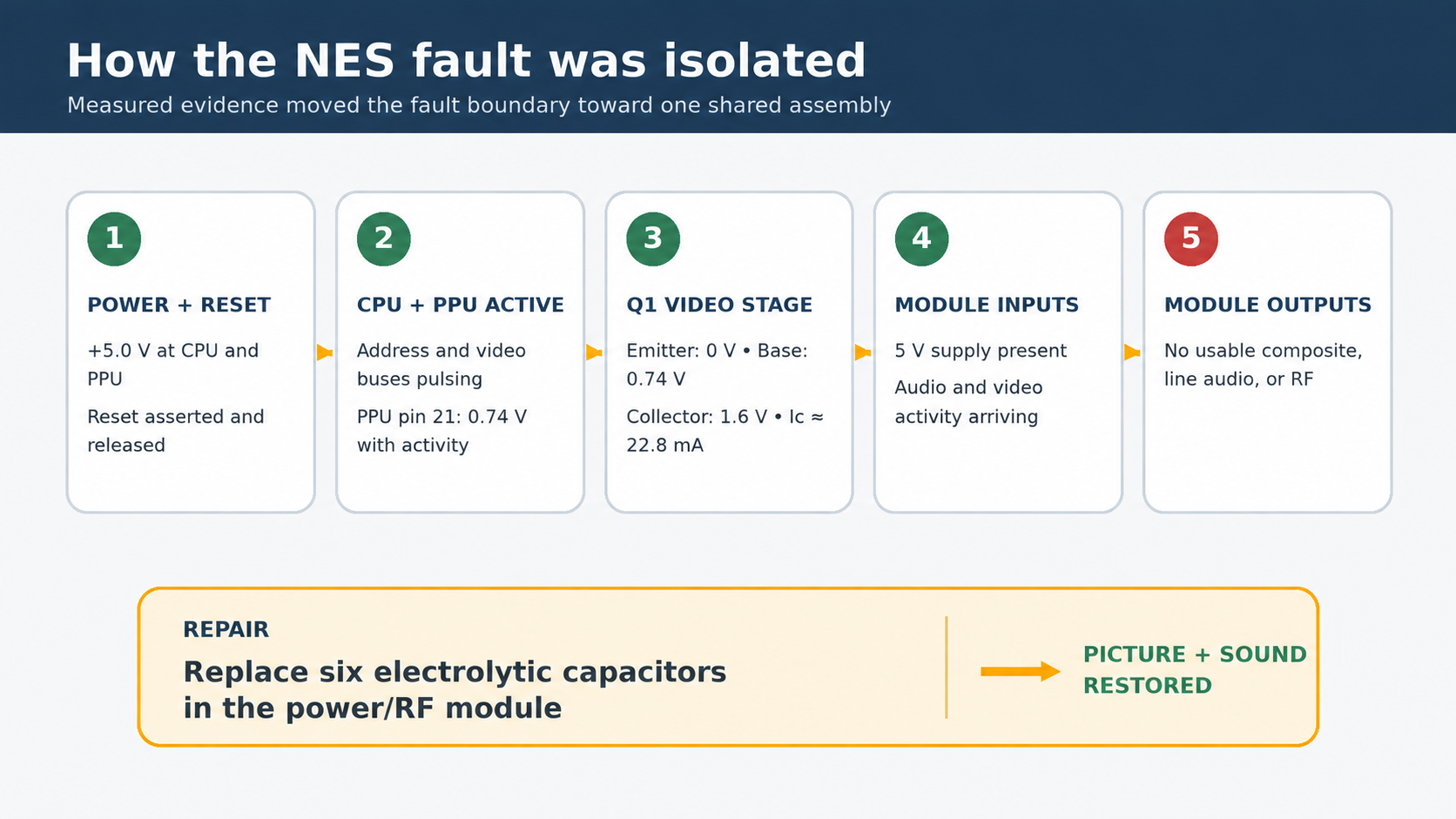
The Long Version
Every Measurement, In Order
What follows is the diagnostic path as it actually ran, including the tests that came back negative. Skip to the result if you'd rather not read the meter readings.
Starting Symptoms
The console arrived doing the classic blinking red power LED. Before opening anything, I did the routine maintenance that should always precede deeper electronic diagnosis:
- Cleaned the cartridge contacts with 99% isopropyl alcohol
- Cleaned the 72-pin connector contacts
- Tried several known-good cartridges
- Tested both the RF/coax and the composite AV outputs
After cleaning, the behavior changed. With a cartridge installed the power LED stayed solid instead of blinking, and the screen showed a brief flash of garbage data before going dead again. With the slot empty the LED kept blinking, which is normal, because the 10NES lockout chip can't complete its handshake with an empty slot and holds the system in a reset loop.
Two things came out of that. The solid LED meant the connector cleaning had accomplished something real: the console was now getting past the CIC lockout. And the momentary flash of screen data meant the video path could still pass something. This was a degraded or intermittent output stage, not a completely severed one. Neither observation explained why the console then sat there with no usable picture or sound.
Ruling Out the Television and the Cartridge Path
I first connected the NES to a Samsung SyncMaster TA350 through its composite breakout adapter, then tested the RF output on analog channels 3 and 4.
Modern televisions make unreliable test displays for old consoles. They're less tolerant than a CRT of low-amplitude composite video, weak synchronization, or an imperfect colorburst, and some can't tune the NES's RF output even when the console is perfectly healthy. A failed RF test on its own is weak evidence.
Here, though, both RF and composite were dead. The same result appeared on a second television, and that display had shown this console working before. A display compatibility problem was unlikely.
I also powered the console with no cartridge in the slot. A working NES with an empty slot still puts out sync and a background raster even while the lockout chip cycles it. This one's output didn't change at all.
That test earned its keep: it separated the video failure from the cartridge, the 72-pin connector, and the CIC handshake entirely. The search moved to the console's shared power, clock, video, and output circuitry.
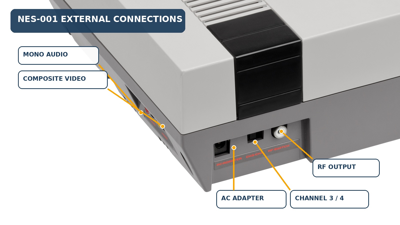
Checking the Power Supply
The first internal check was the 7805 voltage regulator on the motherboard, marked 6J4 S HA 17805 on this console. Its regulated output measured +5.0 V DC.
A correct reading at the regulator doesn't guarantee that power actually reaches every chip, or that the reset circuit is behaving. So I measured directly at the CPU and the PPU.
Power and Reset at the CPU and PPU
| Test point | Reading |
|---|---|
| CPU (RP2A03) pin 40 to ground | +5.0 V DC |
| CPU pin 20 to pin 40 | +5.0 V DC |
| CPU reset line, running | +5.0 V DC |
| CPU reset line, Reset button held | About 5–7 mV DC |
| PPU (RP2C02) pin 22, running | +5.0 V DC |
| PPU pin 22, Reset button held | About 5 mV DC |
The CPU had its full supply at the package, and the reset line on both chips asserted and released cleanly. That ruled out a stuck reset circuit and a missing 5 V rail at the processor, two of the most common causes of a dead-but-powered console.
Confirming the CPU Was Actually Executing
Correct voltages prove a chip is powered, not that it's working. For that I used an Elenco LP-560 logic probe, which shows whether a digital line is sitting high, sitting low, or switching between the two.
CPU pin 31 showed both high and low states with the pulse indicator flashing. I then walked several address lines:
| CPU pin | Logic-probe result |
|---|---|
| Pin 4 | High + low + flashing pulse |
| Pin 5 | High + low + flashing pulse |
| Pin 10 | High + low + flashing pulse |
| Pin 18 | High + flashing pulse |
| Pin 19 | High + flashing pulse |
On the RP2A03, pin 3 is /RES, pin 20 is ground, pin 40 is the supply, and pins 4 through 19 are address lines A0 through A15. Activity across several address lines at once is strong evidence that the CPU is fetching instructions rather than sitting halted.
It also confirms the master clock indirectly. The 2A03 divides the console's 21.48 MHz master clock down internally to drive the bus; with no clock arriving there would be no sustained bus activity to find.
If You Don't Have a Logic Probe
A digital multimeter in DC-volts mode gives a rough version of the same test. With the console running, measure CPU pins 4 through 19. Rapidly toggling address lines get averaged by the meter and usually show up as intermediate voltages, commonly somewhere around 1.5–3.5 V. A halted or unclocked CPU is more likely to leave those lines parked at a steady 0 V or 5 V.
It's no substitute for a scope or a logic probe, but it will separate an active bus from a completely static one. Don't trust a meter's frequency counter here, because most aren't fast enough for the NES's clock lines, so 0 Hz on a megahertz-range signal proves nothing.
Testing the PPU
The PPU's clock input showed pulse activity. I then checked several of its memory-interface signals:
| PPU pin | Logic-probe result |
|---|---|
| Pin 23 | High + slower pulse |
| Pin 24 | High + pulse |
| Pin 27 | High + low + pulse |
| Pin 29 | High + pulse |
| Pin 32 | High + low + pulse |
| Pin 33 | High + low + pulse |
That bus activity showed the PPU was powered, clocked, and actively reading video memory. A chip that had lost its supply or its clock would be silent here.
The standard RP2C02 puts its raw analog composite video out on pin 21. That pin measured 0.74 V DC, with the logic probe registering activity. A TTL probe only gives a crude indication on an analog composite waveform, so the useful finding was a negative one: pin 21 was neither dead at 0 V nor stuck at 5 V. Combined with the bus activity, that was consistent with a PPU generating video normally.
Following the Video Signal Through Q1
Tracing PPU pin 21 led to transistor Q1, the next stage in the video path. Before reading any voltages off it, I mapped its connections with the console powered off:
| Connection | Resistance |
|---|---|
| Emitter to ground | Approximately 0 Ω |
| Collector to +5 V through R2 | 149 Ω |
| Base to PPU pin 21 | Approximately 0 Ω |
That identified emitter, base, and collector from their actual circuit connections instead of from a generic TO-92 package diagram. It matters: transistor pinouts aren't universal, and the Japanese 2SC-series parts used throughout this era frequently run a different lead order than common Western equivalents. Assume the wrong pinout and every voltage you read afterward gets misinterpreted.
| Operating point | Reading |
|---|---|
| Emitter | 0 V |
| Base | 0.74 V |
| Collector | 1.6 V |
| Base–emitter voltage | 0.74 V |
| Estimated collector current | (5.0 V − 1.6 V) / 149 Ω = 22.8 mA |
Those numbers describe a transistor sitting in its expected biased region: conducting, not saturated, not cut off. They also cross-check the previous measurement: the 0.74 V at the base is the same 0.74 V measured at PPU pin 21, exactly as it should be for a base tied directly to that pin. The signal path from the PPU into the video transistor was intact.
R2 and the Limits of In-Circuit Resistance
R2 measured 149.2 Ω, essentially its nominal 150 Ω value.
This is a good illustration of why resistance mode and continuity mode answer different questions. A continuity beeper usually only sounds below a threshold in the tens of ohms, so a perfectly healthy 150 Ω resistor may never beep at all, and reading that as an open circuit sends you chasing a fault that doesn't exist.
In-circuit resistance readings need care for a second reason: the meter's test current can wander off through parallel resistors, semiconductor junctions, and capacitors. Lead polarity and autoranging change which junctions conduct, which is how the same node can give wildly different readings on two consecutive measurements.
What makes a component check trustworthy:
- Unplug the unit and let the filter capacitors discharge.
- Short the meter leads together and note their resistance as a baseline.
- Re-check any questionable reading in both lead polarities.
- Use diode mode for transistor junctions.
- Lift one component lead when you genuinely need an isolated value.
Tracing the Fault into the Power/RF Module
The rectangular metal enclosure at the rear of this NES is marked M 83206085 NES J63TA.
It's usually called the RF modulator, but on the NES-001 it does considerably more than generate a channel 3 or 4 signal:
- Rectifies and filters the incoming 9 V AC from the adapter into the raw DC rail that feeds the motherboard's 7805 regulator
- Buffers and filters the baseband audio and video
- Modulates those signals onto the selected RF channel
- Carries the power jack and the RCA jacks mechanically
That shared audio/video role turned out to be the key to the whole diagnosis. Video from the PPU by way of Q1 and audio from the CPU's mixing network are otherwise completely separate paths through the console. They only meet in one place: inside this module, on the way to the external jacks. A fault in there can kill composite video, line-level audio, and RF output all at once, which is exactly the symptom on the bench.
With the power disconnected, continuity mode found the module's video input: Q1 collector to module video input, 0.0 Ω. The video path was now confirmed end to end:
RP2C02 pin 21 → Q1 base → Q1 collector → power/RF module video input
Measuring the Module Inputs
With the console powered and the meter's black lead clipped to a verified ground, I measured the module's five signal pins:
| Pin | Reading | Identification |
|---|---|---|
| 1 | 11 V DC | Raw rectified supply out to the 7805 |
| 2 | 0.5 mV DC | Ground |
| 3 | 5 V DC | Regulated supply back in from the board |
| 4 | About 30 mV, changing | Audio input |
| 5 | About 1.9 V, changing | Video input |
The 5 V on pin 3 confirmed the module was powered. The unsettled readings on pins 4 and 5 showed audio and video activity arriving at its inputs. A multimeter can't display those waveforms, but movement in an averaged DC value does distinguish a live signal from a static bias voltage.
So: CPU and PPU active, Q1 correctly biased, audio and video both reaching the module, and composite, line audio, and RF all unusable coming out of it. The fault was inside that assembly.
What a Multimeter Can and Cannot Tell You
The yellow composite jack read roughly 0.7–1.0 V in DC mode and about 0.1 V in AC mode. Neither number establishes that valid NTSC video is present, and treating them as if they did is an easy way to draw the wrong conclusion.
Composite video's horizontal line rate is about 15.734 kHz. Plenty of general-purpose multimeters have an AC bandwidth of only a few hundred hertz up to roughly 1 kHz, so their AC ranges simply cannot measure that signal accurately. The DC range shows the waveform's average value, and malformed, unwatchable video can still average out to a perfectly plausible DC number.
Resistance from the module's video input to the RCA center pin was about 800 Ω, and the RCA shield read about 0 Ω to console ground. Those confirmed a passive path through the module; they said nothing about whether its internal output circuitry was producing valid video.
Power-supply ripple is a different story, because full-wave rectifier ripple lands at 120 Hz, comfortably inside a typical meter's AC bandwidth. With both probes on the same point, my setup's AC noise floor was 3 mV. The 7805 output also measured 3 mV AC, meaning its ripple was indistinguishable from the measurement floor. The raw rail sat at 11 V DC and the regulated rail at 5 V DC. All of that showed the console had usable power. None of it evaluated capacitor ESR, or the small electrolytic coupling capacitors sitting in the audio and video paths.
The Evidence Before Opening the Module
| Element | Finding |
|---|---|
| +5 V rail | 5.0 V DC and stable |
| +5 V ripple | At the meter's noise floor |
| Raw rectified rail | 11 V DC |
| Module ground | Good continuity to board ground |
| Module supply | 5 V present |
| CPU, PPU, and clock | Running; address and video buses active |
| Q1 video stage | Correctly biased and conducting |
| Video at module input | Present and changing |
| Audio at module input | Present and changing |
| Composite, line audio, RF outputs | Unusable |
| Cartridge, connector, CIC | Excluded by the no-cartridge test |
| Display | Excluded using two televisions |
Everything measurable from outside pointed at the power/RF module, and specifically at the circuitry its audio and video paths share.
Opening and Recapping the Power/RF Module
The board inside this module is the Mitsumi REV 4, identified from its silkscreen, its layout, and its capacitor designators. It carries a 2200 µF main filter capacitor, two 100 µF capacitors, and three 10 µF audio/video coupling and filtering capacitors.
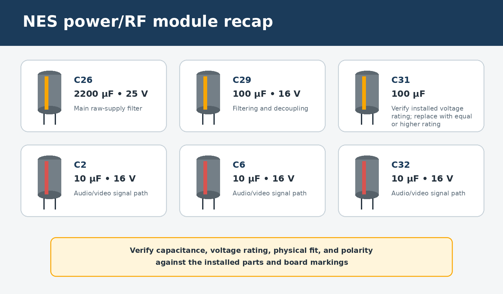
The three 10 µF parts were the prime suspects, because they sit directly in the signal circuitry feeding the failed audio and video outputs. The larger capacitors had the same four decades on them, so I replaced all six as a set rather than leaving same-age parts in service to fail next year.
Matching Parts to the Actual Board, Not to a Parts List
Reference documentation for NES power/RF modules varies, because Nintendo shipped several board revisions and component combinations. On this module, the removed C31 was rated at 10 V even though some published lists specify 25 V, and the 100 µF parts didn't exactly match every reference either.
On vintage electronics, the installed components, the board markings, and the circuit position have to be read together. I matched capacitance values, used equal or higher voltage ratings, and confirmed each replacement physically fit the space available.
Reference
Sorting out which revision you're actually holding is the fiddly part, and GameTechUS's walkthrough Nintendo NES-001 front loader cap replacement inside audio video power module is what settled it here. The closing section lays the different NES power board layouts side by side, which is how I confirmed this console carries the Mitsumi REV 4 board and checked the capacitor placement and types against it before ordering parts. Credit where it's due. It saved a round of guesswork.
Getting at C32
Five of the six capacitors are reachable through the opening left after the 2200 µF part comes out. C32 sits in the opposite corner and needs the module's top shield lifted. Lifting that sheet-metal shield is a different job from desoldering the whole module off the NES motherboard. Leaving the module attached avoids working on its large ground tabs and reduces the chance of damaging the older board's plated connections.
Residue Under the Main Filter Capacitor
With the 2200 µF capacitor out, there was residue on the board beneath it. Residue in that spot is either factory rosin flux or leaked electrolyte, and the difference matters: cured rosin is hard and electrically insulating, while electrolyte can stay tacky, turn conductive, and corrode copper. I cleaned the area with high-purity isopropyl alcohol and inspected the nearby traces and pads under magnification before fitting the replacement. Whichever it was, clearing it made it possible to verify that the copper and the solder joints underneath were sound.
Notes on Recapping a 40-Year-Old Board
Old boards punish shortcuts. A few practices that mattered on this one:
- Clear each through-hole before inserting the new lead.
- Solder wicks through a clean opening by capillary action. I used a desoldering tool until light was visible through each hole, then verified the opening with a trimmed component lead.
- Match the iron tip to the joint's thermal mass.
- The large filter capacitor connects to copper that pulls heat away fast. A 2–3 mm chisel tip makes far better contact with both pad and lead than a fine conical tip.
- Add fresh solder and flux before desoldering an old joint.
- Fresh solder improves heat transfer and helps decades-old solder flow cleanly instead of crumbling.
- Use enough heat to work quickly.
- A brief, controlled application of heat is easier on an aged pad than holding an underpowered tip against it. If a joint doesn't flow promptly, let it cool, add flux, and try again. That's how you avoid lifting pads.
- Verify polarity before soldering, every time.
- On polarized electrolytics the stripe marks the negative lead. Here the negative pads of the supply-filter capacitors could also be confirmed by continuity to ground; the smaller signal-path capacitors needed careful comparison against the board's polarity markings and the original parts.
The Result
After cleaning the module and replacing all six electrolytic capacitors, I reassembled the console and tested it again with known-good cartridges.
Picture and sound came back. The NES produced usable audio and video and loaded games normally, which confirmed both halves of the conclusion: the failure was inside the power/RF module, and the recap corrected it. Nothing was replaced outside the one assembly the measurements pointed at.
What This Job Shows About How We Work
A power light is a starting point, not a diagnosis.
Direct measurements of supply voltage, reset, clock, and bus activity say far more about what a device is actually doing than any front-panel indicator.
Simple tests eliminate entire subsystems.
Powering the console with an empty cartridge slot separated the video failure from the connector and the lockout handshake. Testing a second display removed another whole variable. Neither test cost anything but a few minutes.
Knowing an instrument's limits is part of using it.
A multimeter measures DC rails and 120 Hz ripple accurately; it cannot validate a 15.734 kHz video waveform. Reading a number without knowing what the meter can actually see is how people replace the wrong part.
Map a component's connections before interpreting it.
Identifying Q1's emitter, base, and collector from continuity and resistance made its operating voltages meaningful without trusting a package pinout that may not apply.
A stable 5 V rail does not mean every capacitor is healthy.
This module regulated its supply pins perfectly while aged signal-path capacitors kept any useful audio and video from reaching the outputs.
Evidence decides what gets replaced.
Each test cut down the list of possible causes, and the repair addressed the section of the circuit the evidence identified. That's how we keep a job from turning into an open-ended parts bill, and how a console that could easily have been written off went home working.
Not Sure Yours Is Worth Fixing?
Consoles, laptops, TVs, appliance control boards, generators, amps: the process on this page is the process on all of them. We'll tell you honestly what we find, including when the repair isn't worth it. See what diagnosis and repair cost before you book.
Not sure it's worth fixing? Tell us the make, model, and what it's doing, or call (509) 708-2953 — no charge to ask, and nothing to book. Send us the details →
That conversation can usually tell you whether a repair is worth pursuing and which diagnostic fits. A firm repair price takes having the device in hand.
Nothing is charged when you book a drop-off. The $50 diagnostic, and the pickup fee if you'd like us to collect the device and bring it back, are billed on your final invoice. No transport charge if you bring it to Leavenworth yourself.